There are several ways to connect the Inertial Measurement Unit (IMU) to the Jetson TK1 Development Kit. Here’s a demonstration of a very simple way. Looky here:
Background
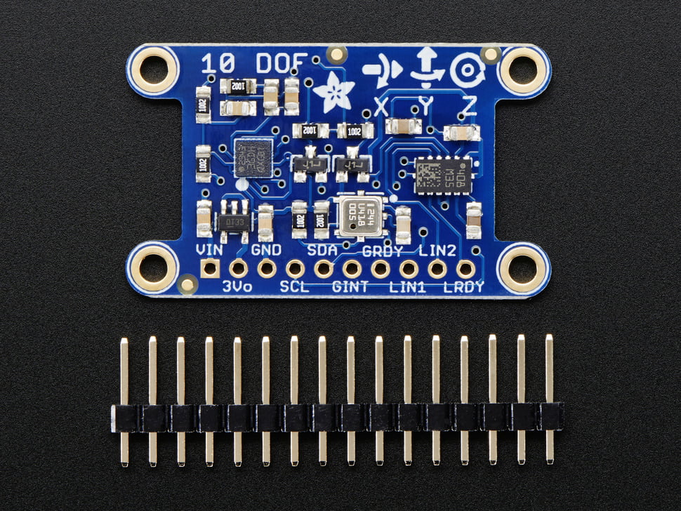
For the IMU, the The Adafruit 10-DOF IMU Breakout is being used. Here’s a couple of pictures of the breakout board from the Adafruit website:

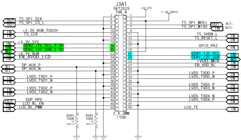
Solder the supplied header pins onto the IMU breakout board, then wire the IMU header pins to the Jetson J3A1 connector as follows:
GND J3A1-14 (-)
VCC J3A1-16 (+)
SCL J3A1-18 (C)
SDA J3A1-20 (D)
Unfortunately my soldering skills are so poor that providing a video of that process would probably be the canonical way *not* to solder. Note: Here’s a page with some information on how to get started soldering and working with electronic components if you need some help..
Here’s some pictures from the Jetson Wiki for reference :

There are several ways to actually connect the headers to the Jetson J3A1 connector, in this case we use simple female to female jumper wires (0.1″ spacing, 2.54mm pitch – this is standard Arduino size) to attach to the IMU header, and then connect the jumper wire to a machine pin jumper wire, which is then connected to the Jetson.
For the demo, I used Adafruit Premium Female/Female Jumper Wires – 40×6″ and 20 CM Machine Pin Wire Kit/10 Pack. This approach may be adequate for some projects, but for more rugged projects you may want to consider actually soldering wires to the header pins approach or making a breakout board for the Jetsons’ J3A1 header. Remember that the J3A1 header is 2mm pitch (0.08″) which is slightly smaller than the more standard DIY 2.54mm pitch that something like an Arduino uses. You’ll also want to physically mount the device some where also, fortunately there are mounting holes for that purpose on the breakout board.
Once you have the IMU connected to the Jetson, you’re ready to calibrate. Go over to Intertial Measurement Unit (IMU) – Part II to get a feel for how that is done.
One Response