


Interfacing with the Jetson TX1 GPIO (General Purpose Input/Output) subsystem can be accomplished with a small “C” programming language library and knowledge of the J21 expansion header. Looky here:

Background
In a previous JetsonHacks article GPIO Interfacing – NVIDIA Jetson TK1, we covered how to interface with the Jetson TK1 GPIO subsystem. This article discusses interfacing with the Jetson TX1 in a similar manner.
Note: The usual warning, you are dealing with electricity and all that, there is a chance you could fry your Jetson by hooking it up incorrectly. Be strong, be brave, but also be very careful.
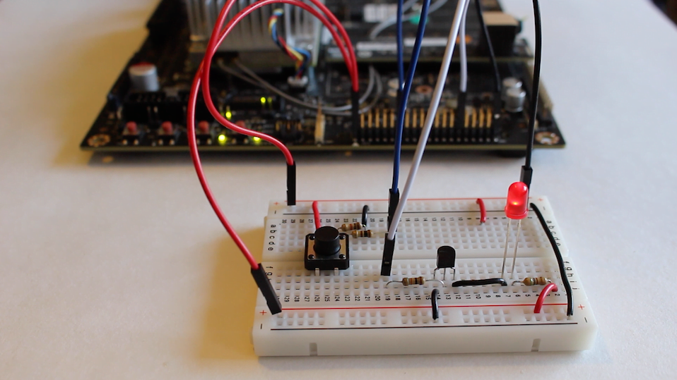
In the demonstration, a simple GPIO library interface for the Jetson TK1 was created, and a little hardware/software demo was built. The hardware consists of a couple of circuits, a LED driven by a GPIO pin on the Jetson, and a button switch which is read from another GPIO pin on the Jetson.
Jetson TX1 GPIO Layout
The Jetson TX1 J21 Header signal layout is described on this page: J21 Header Pinout.
There are few documents which are used to derive the list of GPIO header signals on the J21 Header of the Jetson TX1 Development Kit. J21 is a 40 pin header. The documents are all available from the NVIDIA Embedded Download Center.
- Jetson TX1 Module Pinmux – Spreadsheet which lists how signals are routed from the TX1 Module to the Jetson Carrier Board
- Jetson TX1 Developer Kit Carrier Board Specification – Information about the Carrier Board and Interface Connectors. Section 3.4 Expansion Header gives the Expansion Header Pin Descriptions in table form.
- Jetson TX1 Developer Kit Carrier Board Schematics and Layout Files – Schematics for the Carrier Board (useful, but may not be necessary for the given task)
- The kernel source file: drivers/pinctrl/pinctrl-tegra210.c contains the signal name to gpio number mappings
There are 8 GPIO signal pins on the Jetson TX1 J21 Header:
| Jetson TX1 J21 Header | |||
|---|---|---|---|
| Sysfs GPIO | Pin | Jetson Signal Name | PUPD |
| gpio36 | Pin 32 | AO_DMIC_IN_CLK | PULL_DOWN |
| gpio37 | Pin 16 | AO_DMIC_IN_DAT | PULL_DOWN |
| gpio38 | Pin 13 | GPIO20/AUD_INT | PULL_DOWN |
| gpio63 | Pin 33 | GPIO11_AP_WAKE_BT | PULL_DOWN |
| gpio184 | Pin 18 | GPIO16_MDM_WAKE_AP | PULL_DOWN |
| gpio186 | Pin 31 | GPIO9_MOTION_INT | PULL_UP |
| gpio187 | Pin 37 | GPIO8_ALS_PROX_INT | PULL_DOWN |
| gpio219 | Pin 29 | GPIO19_AUD_RST | PULL_UP |
The Signal Name represents the name of the signal on the Jetson TX1. The signal names are provided as the suggested interface pin for people who are designing and adding the given named functionality to the Jetson. This does not mean that the GPIO pins are dedicated, all GPIO pins are generic. In other words, the names do not signify any built in functionality.
Sysfs GPIO is the name of the virtual file that can be used to access the GPIO port. The file is accessed in the ‘/sys/class/gpio’ directory.
Signals on the header can be configured to run at 3.3V or 1.8V by shorting the appropriate pins on the J24 header. For this example, 3.3V is selected, which is the standard configuration.
Signals on the J21 header can be configured with a resistor as a PULL_DOWN, PULL_UP, or NORMAL circuit. The standard configuration is noted in the table. The resistance value is 4KΩ.
All of the signals are enabled for E_input.
The Jetson TX1 includes the ability to export GPIO control and status for use in an application using sysfs. No other driver can be using the GPIO of interest.
Pinmux
In the Jetson community, you may run across the term ‘Pinmux’. On the Jetson TX1 module, there are more signals on the chip than there are on the carrier board. A multiplexer (or “mux”) is a device that selects one of several input signals and forwards the selected input into a single line. The Pinmux table is used to describe which pins are selected on the processor and how to route them to the board using the multiplexer. This table is typically described in a source code format which once compiled into a data structure can be used by the operating system for signal routing. This data structure, called the ‘Device Tree’, is loaded at boot time by the operating system.
Source files for the Device Tree are located in the kernel source for L4T, and have a .dts or .dtsi extension. Compiled .dts files have a .dtb extension. In addition to the base Device Tree, overlays can be created to add additional functionality without having to recompile the entire Device Tree or maintain a monolithic binary blob. The pinmux description can be changed for different signal routing depending on the system needs. For this article, it is assumed that the standard configuration is being used.
Parts
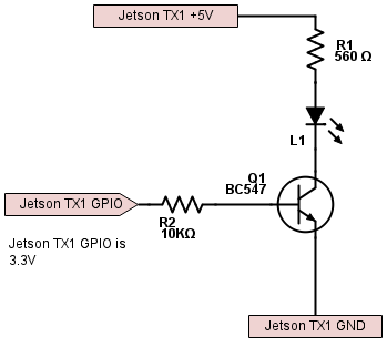
For the LED circuit:
- 2.3V 16ma LED
- BC547 transistor
- 10KΩ resistor
- 560Ω resistor
For the button circuit:
- Tactile Button Switch
- 100Ω resistor
- 1KΩ resistor
Note: All resistors are 1/4 watt
Jumper Wires, 2.54mm 1p to 1p male to female
Breadboard (In the video, a Solderless BreadBoard, 400 tie-points, 4 power rails
Multimeter (Optional, a Fluke 115 Electricians True RMS Multimeter

The The Arduino Starter Kit
GPIO Interfacing Wiring
Here are some pseudo schematics of the circuits:


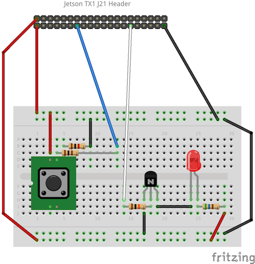
If we look at the Jetson TX1 J21 header pinout, we see that Pin 13 is gpio38. We will use this as our button input to the Jetson. We also see that Pin 29 is gpio219, which we will use to drive the LED.
Breadboard Layout


Software Installation and Demonstration
The GPIO library and example code to run the breadboard prototype is stored on the JetsonHacks Github account. To clone the repository:
$ git clone git://github.com/jetsonhacks/jetsonTX1GPIO.git
To build the example:
$ cd jetsonTX1GPIO
$ ./build.sh
Once the example has been compiled, run the example:
$ sudo ./exampleGPIOApp
The ‘sudo’ is needed to get permission for accessing the GPIO subsystem. The example application will start up and flash the LED a few times. Next, the user can tap the button to turn the light on and off, the button pressed is ‘on’, the button not pressed is ‘off’. The application runs until the user hits the ‘Esc’ key on the keyboard.
Other GPIO Pins
There are other GPIO signals available on the camera and display connectors on the Jetson TX1. These signals can be accessed much the same way in software as the ones on the J21 header, but are a little harder to interface with through the fine pitch board connectors.
Conclusion
This is a simple way to interface with GPIO on the Jetson, try it out! The code is provided for the library, as is the example application. Note that this is a very simplistic version of a GPIO interface library. There are many types of device interface strategies for using GPIO, this is a starting basis for how it could be approached.
Notes
The demonstration was performed on a Jetson TX1 development kit running L4T 23.1.