


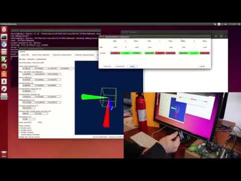
This blog entry is a little backwards, in that it is labeled Part II. Actually, it’s part III. If you looked at Inertial Measurement Unit (IMU) – Part I, you would expect to see how to hook up the IMU to the Jetson. Instead, I’ll show you what happens after you hook up the IMU to the Jetson, so that you know you’ve successfully hooked it up. Looky here:
Background
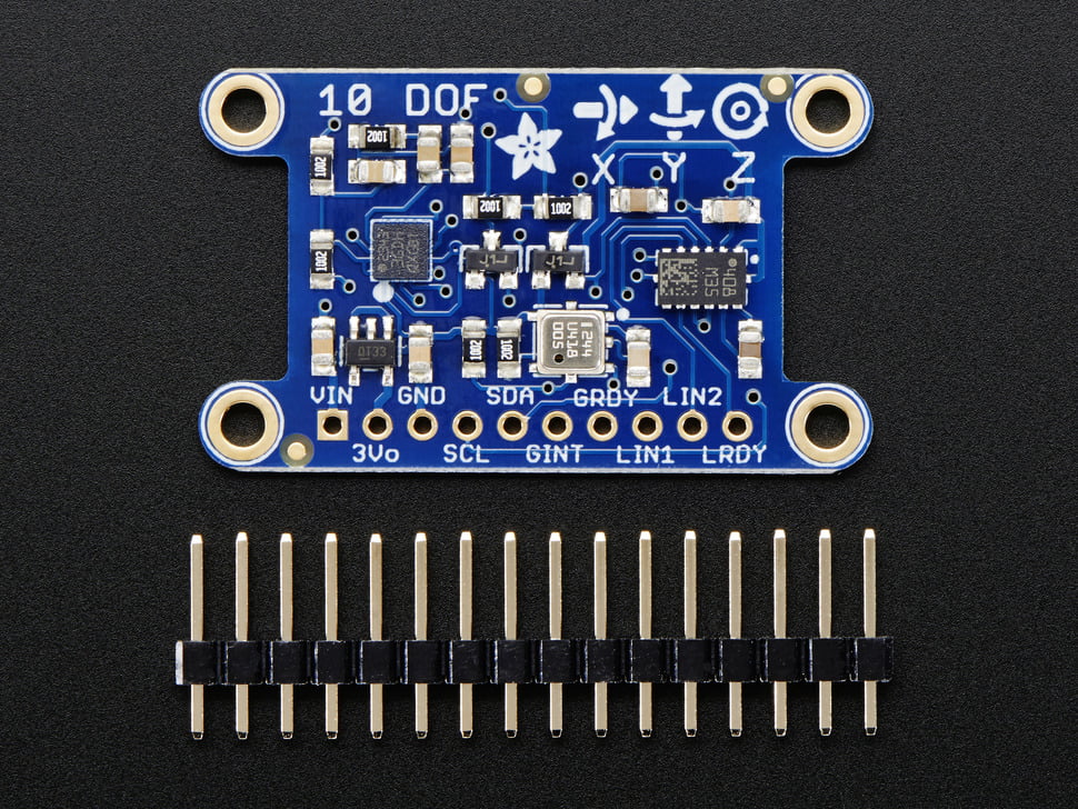
For the IMU, the The Adafruit 10-DOF IMU Breakout is being used. We’ll go over hooking up the IMU to the Jetson in a later post, but it’s pretty easy. Bascially solder the supplied header onto the IMU, then wire the IMU header pins to the Jetson JA31 connector as follows:
GND J3A1-14 (-)
VCC J3A1-16 (+)
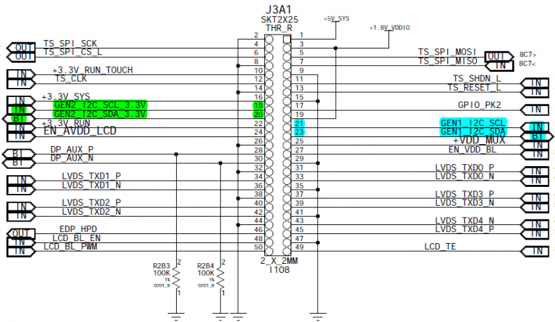
SCL J3A1-18 (C)
SDA J3A1-20 (D)
Here’s some pictures from the Jetson Wiki:

There are several ways to actually connect the wires to the pins, you can use headers, machine pin jumper wire, and a mix of simple Arduino jumpers connected to the appropriate header insert. We’ll look at this in a later blog entry.
Calibration
Anyway, once the IMU is hooked up, the next step is to calibrate the IMU. If you have seen people rotating their quadcopter or model airplane and ‘posing’ them, this is what they are doing. There’s such a large amount of information that’s out there about the subject that there’s not much to add, other than you’ll have to calibrate the IMU. Basically the accelerometers need to be told the proper range of values when no artificial acceleration is being applied, and the magnetometers also need a little help. Here’s the RTIMULib calibration instructions, use them. Here’s why you want to calibrate the magnetometer.
Conclusion
The IMU is very useful for finding out pose (orientation in space), and now they are almost ubiquitous in any type of sophisticated electronic or robotic device. It is one of the very useful tools in the electronic sensor toolbox. They are also lots of fun to play with. Click here for Part III.