In the fifth part of our Jetson RACECAR build, the lower platform mounting commences, along with the attachment of a Jetson Development Kit. Looky here:
Background
As we discussed about in Part 4 of the Jetson RACECAR build, we are mounting the lower platform to the suspension towers of the TRAXXAS Rally chassis. Two Traxxas 6815R Body Mounts![]() are used as mounting points for the platform along with some Hex Socket Button Head Screws, 3x8mm
are used as mounting points for the platform along with some Hex Socket Button Head Screws, 3x8mm![]() to mount the body mounts to the suspension towers. A body mount was attached to the front suspension tower, the other was attached to the rear suspension tower after removing the stock body mounts.
to mount the body mounts to the suspension towers. A body mount was attached to the front suspension tower, the other was attached to the rear suspension tower after removing the stock body mounts.
There will be at least two platforms. A lower platform will mount the Jetson computer, batteries, camera(s) and other components. An upper platform will serve a couple of functions. First, the second platform will act as protection in case of a roll over incident. Second, the platform will serve as an attachment point for wireless antennas and the IMU. This placement helps get the IMU further away from the cars motor, which can cause interference with the IMUs magnetometer.
Please note that this is purely prototypical work being done with materials on hand, the idea being to get a feel for what layout and component placements are suitable for this application. This can be done in a variety of ways, some of which are probably more flexible and/or less expensive.
Layout and Lower Platform Mounting
Once the body mounts were attached to the chassis, the platform attachment points were laid out by centering the platform over the chassis and marking the body mount attachment points on the platform. Once the points were marked, holes were drilled and the platform was attached to the body mounts for a test fit. As discussed in the previous article, a 5/8″ standoff was attached to both of the front platform mounting points to help level the platform. In retrospect, a 1/2″ standoff is probably a better selection.
After the test fit, the platform was removed. As seen in the video, the first electronic component layout basically centered everything over the platform center line. Components are mounted on 1/4″ male/female standoffs which use a captive nut on the underside of the platform to keep the standoff in place. This is not optimal, and the mounting mechanisms will need a thorough sorting out before building the full car. Also, some attachments were made using different types of metal (e.g. aluminum standoffs with stainless steel nuts), which needs to be rectified in upcoming builds.
After the standoffs were installed, the platform was reattached to the chassis. The Jetson was installed. In this instance, a NVIDIA Jetson TK1 Development Kit![]() is being used, but a NVIDIA Jetson TX1 Development Kit
is being used, but a NVIDIA Jetson TX1 Development Kit![]() can be used. There are variations that will be needed for wiring and mechanicals depending on the selection.
can be used. There are variations that will be needed for wiring and mechanicals depending on the selection.
The battery mounting platform is then installed.
As seen in the video, there was an issue with mounting the PWM Driver. The PWM Driver is used to control the steering servo and the motor controller. The issue is that the screws that were being used with the standoff is too large for the PCA9685, so this issue will need to be addressed in upcoming articles.
As a note, most of the blog entries and project builds are captured while the work is being done, with a minimal amount of staging for the camera. Same thing with box openings, I am usually seeing the objects inside the box for the first time, along with you. The shots are usually the “first time through”, so when mistakes happen you see them. It is my wish that you see the “uh-oh” part of these projects, when you are working and planning and things don’t turn out like they should. I think that is typical of the way these projects progress. This also shows the constraints of what happens when things don’t go as “planned”, and the resourcefulness needed to overcome the resultant hurdles.
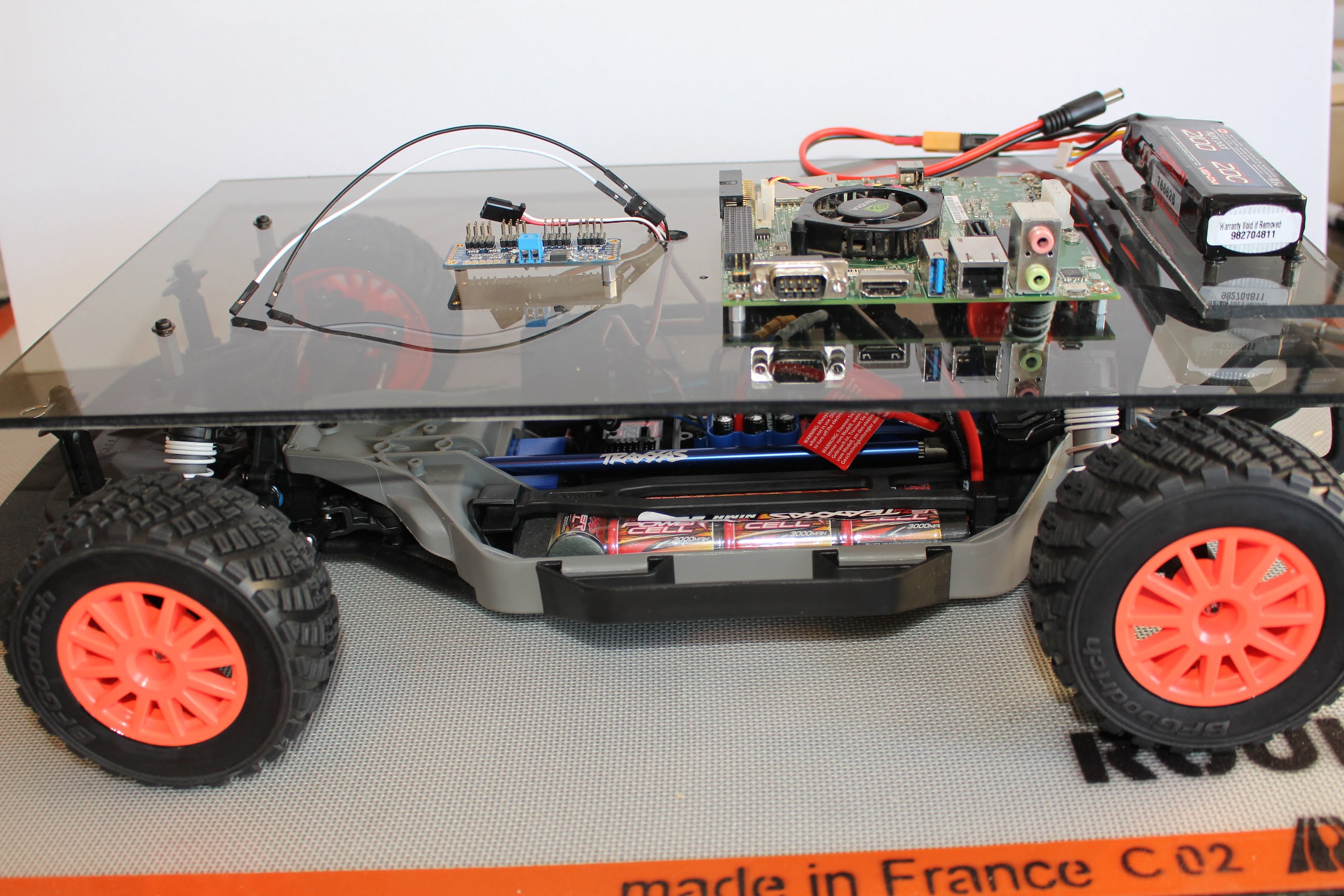
After installing the lower platform and Jetson, here’s what the Jetson RACECAR looks like: