


Robot Operating System (ROS) makes integration of sensors such as the Bosch BNO055 9 Degree of Freedom (DOF) IMU straightforward. Looky here:

Background
When building a robot, designing, planning and selecting sensors and parts for the build are crucial to success of the overall project. In building our project robot, one of the sensors that is needed is an Inertial Measurement Unit (IMU) which will be used for odometery. Odometry will be discussed in another article in the future.
There are a multitude of IMUs on the market, in a three part article about IMUs, we discussed how to install a 10-DOF IMU. That particular IMU has discreet gyroscope and accelerometer/compass chips from which the host takes the readings and applies ‘fusion’ algorithms to produce three-axis orientation output. Also, the host generally has to provide a means to calibrate the sensor. Calibration usually means moving the IMU around each axis to hit the minimum and maximum values of the sensor, and place the information into a calibration file of some sort.
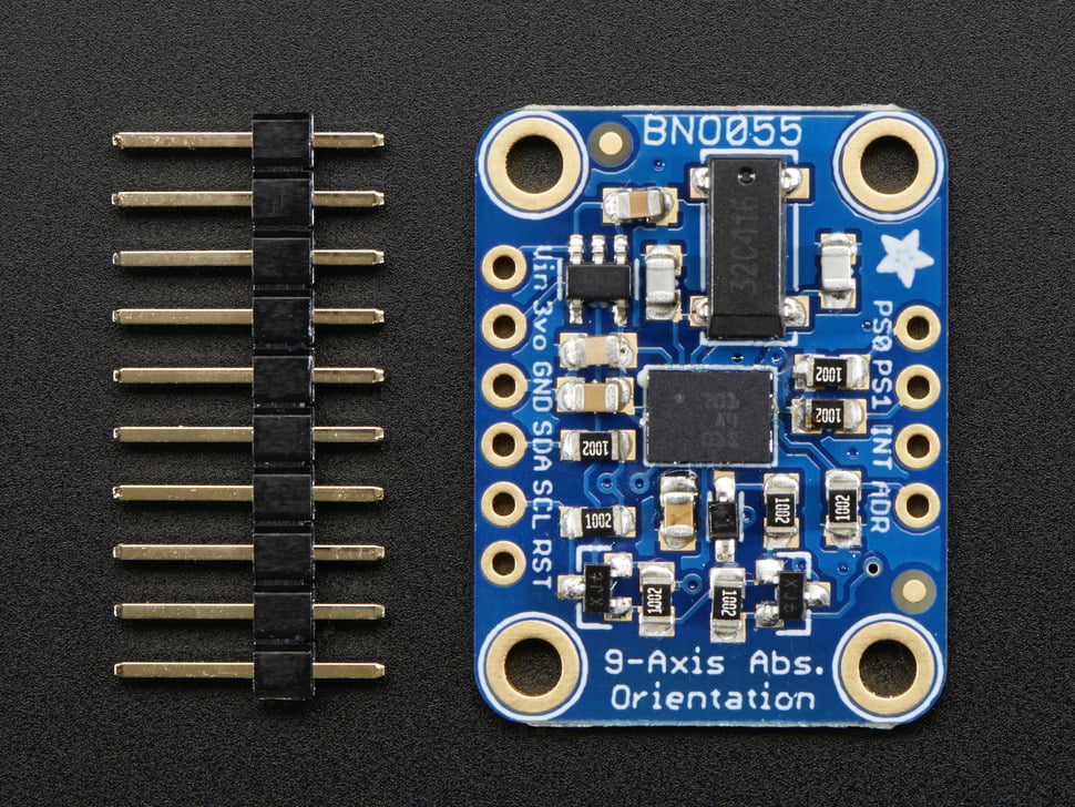
Bosch has recently come out with a new IMU, the BNO055. Adafruit has placed the BNO055 on a breakout board and added their usual niceties which allows the Jetson TK1 to access the BNO055 via I2C. The descriptive blurb from the Adafruit website:
If you’ve ever ordered and wire up a 9-DOF sensor, chances are you’ve also realized the challenge of turning the sensor data from an accelerometer, gyroscope and magnetometer into actual “3D space orientation”! Orientation is a hard problem to solve. The sensor fusion algorithms (the secret sauce that blends accelerometer, magnetometer and gyroscope data into stable three-axis orientation output) can be mind-numbingly difficult to get right and implement on low cost real time systems.
Bosch is the first company to get this right by taking a MEMS accelerometer, magnetometer and gyroscope and putting them on a single die with a high speed ARM Cortex-M0 based processor to digest all the sensor data, abstract the sensor fusion and real time requirements away, and spit out data you can use in quaternions, Euler angles or vectors.
Note: The BNO055 uses an I2C technique called ‘clock stretching’. The chip holds the SCL line low while taking a reading, basically saying “not ready yet”. This provides more flexibility on the I2C master side because it does not have to do a full command-and-response. However, be aware of this when connecting the BNO055 to things like I2C address multiplexers which may require you to work around this feature. For example, some people report that initializing the BNO055 twice may be required as a work around to get the sensor to work.
I like things that do the maths on their own and don’t bother me about it. Cool!
Install Strategy
The idea here is to install the Bosch IMU under ROS on the Jetson TK1. Following the path of least resistance, we’ll use RTIMULib (from richards-tech LLC on Github) as the low level interface library and rtimulib_ros (from Romain Reignier) as the interface to ROS. It should be noted that this is a trade off of convenience versus overhead. Because the Bosch IMU spits out fused sensor data, it should be straightforward to turn this directly into a producer that ROS can digest. However RTIMULib and rtimulib_ros already do this (though with added overhead), so for now this seems like a straightforward path to integration.
We will cover the software installation, how to wire up the Bosch IMU to the Jetson, and then how to run the visual demo.
Software Installation
Note: Before installing the IMU interface to ROS, ROS must be installed of course. Here’s an article on how to do that. Also you must have a catkin workspace installed. Here’s a video that covers that process.
Installing RTIMULib
Under the normal RTIMULib installation process, Qt is installed along with the library. If you are not using Qt on the robot, that is unnecessary. In this installation, the cmake file is modified to so that Qt is not installed.
First install ccmake, which will be used later to edit the cmake file.
sudo apt-get install cmake-curses-gui
Then get RTIMULib.
git clone https://github.com/jetsonhacks/RTIMULib.git
By default, I2C devices are owned by root. To change this, create a file /etc/udev/rules.d/90-i2c.rules and add the line:
sudo gedit /etc/udev/rules.d/90-i2c.rules
KERNEL==”i2c-[0-7]”,MODE=”0666″
As an alternative, you can do this straight from a command line:
$ sudo bash -c 'echo KERNEL==\"i2c-[0-7]\",MODE=\"0666\" > /etc/udev/rules.d/90-i2c.rules'
Then prepare for compilation
$ cd RTIMULib
#Switch to the Linux directory
$ cd Linux
$ mkdir build
$ cd build
$ cmake ..
This generates the cmake file. The parameters can now be changed so that Qt is not required:
ccmake ..
Change the ‘GL’ related options to off, ‘c’ to configure and then ‘g’ to generate and exit. Then:
cmake ..
make -j4
sudo make install
sudo ldconfig
You will probably need to reboot the machine for the permission changes in the udev to take effect.
Install rtimulib_ros
Setup rtimulib next. “catkin_ws” is the example workspace name and should be replaced by your own catkin workspace name where you are doing development.
cd ~/catkin_ws/src
source devel/setup.bash
git clone https://github.com/jetsonhacks/rtimulib_ros.git
To recreate the demonstration, the ROS Topic needs to be “imu”. In the source file, it is listed as “imu/data”. The Topic name is probably related to the consumer viewing the Topic, you may need to change this appropriately later. For now, we’ll just get this working for the demo.
cd rtimulib_ros/src
$ gedit rtimulib_ros.cpp
Change the line:
// ros::Publisher imu_pub = n.advertise(“imu/data”, 1);
ros::Publisher imu_pub = n.advertise(“imu”, 1);
Then build the node:
$ cd ..
$ cd ..
$ catkin_make
For the demo, install the IMU visualizer:
$ sudo apt-get install ros-indigo-razor-imu-9dof
$ sudo apt-get install python-visual
$ sudo apt-get install python-wxtools
Installing the Bosch IMU
There are several ways to connect the Inertial Measurement Unit (IMU) to the Jetson TK1 Development Kit. Here’s a demonstration of a very simple way. The IMU is not the Bosch, but is very similar and the installation method is the same. Looky here:

Here’s a couple of pictures of the Bosch breakout board from the Adafruit website:

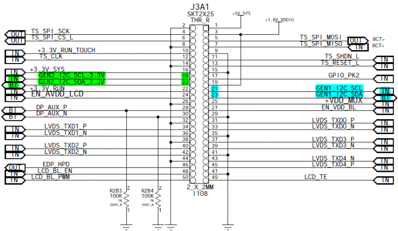
Solder the supplied header pins onto the IMU breakout board, then wire the IMU header pins to the Jetson J3A1 connector as follows:
GND J3A1-14 (-)
Vin J3A1-16 (+)
SCL J3A1-18 (C)
SDA J3A1-20 (D)
Here are some pictures from the Jetson Wiki for reference :

There are several ways to actually connect the headers to the Jetson J3A1 connector, in this case we use simple female to female jumper wires (0.1″ spacing, 2.54mm pitch – this is standard Arduino size) to attach to the IMU header, and then connect the jumper wire to a machine pin jumper wire, which is then connected to the Jetson.
For the demo, I used Adafruit Premium Female/Female Jumper Wires – 40×6″ and 20 CM Machine Pin Wire Kit/10 Pack. This approach may be adequate for some projects, but for more rugged projects you may want to consider actually soldering wires to the header pins approach or making a breakout board for the Jetsons’ J3A1 header. Remember that the J3A1 header is 2mm pitch (0.08″) which is slightly smaller than the more standard DIY 2.54mm pitch that something like an Arduino uses. You’ll also want to physically mount the device some where also, fortunately there are mounting holes for that purpose on the breakout board.
Running the demo
After installing the software and wiring the IMU to the Jetson, you should be ready to start robotin’.
# Open a new terminal
$ roscore
# Open a new Terminal
$ cd ~/catkin_ws
$ source devel/setup.bash
$ roslaunch rtimulib_ros rtimulib_ros.launch
# Open a new Terminal
$ cd ~/catkin_ws
$ source devel/setup.bash
$ roslaunch razor_imu_9dof razor-display.launch
At this point, you should be up and running and you should be receiving data from the IMU.
Conclusion
The Bosch BNO055 is a good choice for many applications where the host system does not want to bother with having to generate the IMU sensor fusion data. The Bosch is straightforward to use, and does not require the calibration gymnastics that most other IMUs require. Recommended.